The voice coil, as a key component of the speaker, directly affects the performance and rated power of the speaker, and there is a close relationship between the two.
According to the national standard GB/T 12060.5-2011 "Methods for Testing the Main Performance of Loudspeakers," the power endurance of a speaker refers to the rated noise power. According to this standard, the rated noise power is equal to \( \frac{U_n^2}{R} \), where \( U_n \) is the rated noise voltage, and \( R \) is the rated impedance. The rated noise voltage is the signal voltage of the simulated program signal fed back to the speaker within the rated frequency range without causing thermal and mechanical damage.
It should be pointed out that the test signal is a simulated program signal, not pink noise. The simulated program signal is obtained from pink noise through an appropriate weighting network, and it is closer to the actual usage of the speaker.
In addition, according to this standard, the power test duration is 100 hours.
For speakers, all technical indicators of the speaker system are important, but there is no doubt that the reliability and lifespan of the speaker are paramount. If a speaker breaks down immediately after use, users will certainly not be satisfied.
Sudden death in humans is mainly caused by heart attacks. The voice coil, known as the heart of the speaker, also determines the lifespan of the speaker. There are several situations that can cause damage to the voice coil: the lead wire breaking at the lead-out point; the voice coil overheating and unwinding; the voice coil wire separating from the former; partial burnout of the voice coil wire; the causes of voice coil damage are usually due to overheating and vibration.
The power that the voice coil can withstand is limited, and the setting of the rated noise power of the voice coil should be scientific, rational, and realistic.
The voice coil should have considerable thermal strength, that is, although the voice coil will heat up due to the passage of current during operation, it will not deform, the adhesive will not fall off, and the paint film will remain intact. The voice coil will dissipate heat through the air (magnetic fluid) in the magnetic gap via the magnetic circuit during operation. A dynamic balance can be maintained under good design and process conditions.
Below is one method for designing voice coil parameters. The thermal power of the voice coil is
\( P_e = J^2 \rho_e S L \) (W)
Where \( J \) is the current density (A/m²);
\( \rho_e \) is the resistivity of the wire (Ω·m);
\( S \) is the side area of the coil (m²);
\( L \) is the length of the voice coil wire (m).
The ratio \( \frac{P_e}{S} \) is called the heat transfer rate \( P_t \).
\( J \) is the current density, that is, the current intensity allowed to pass through the voice coil, which generally ranges from 30A/mm² to 90A/mm².
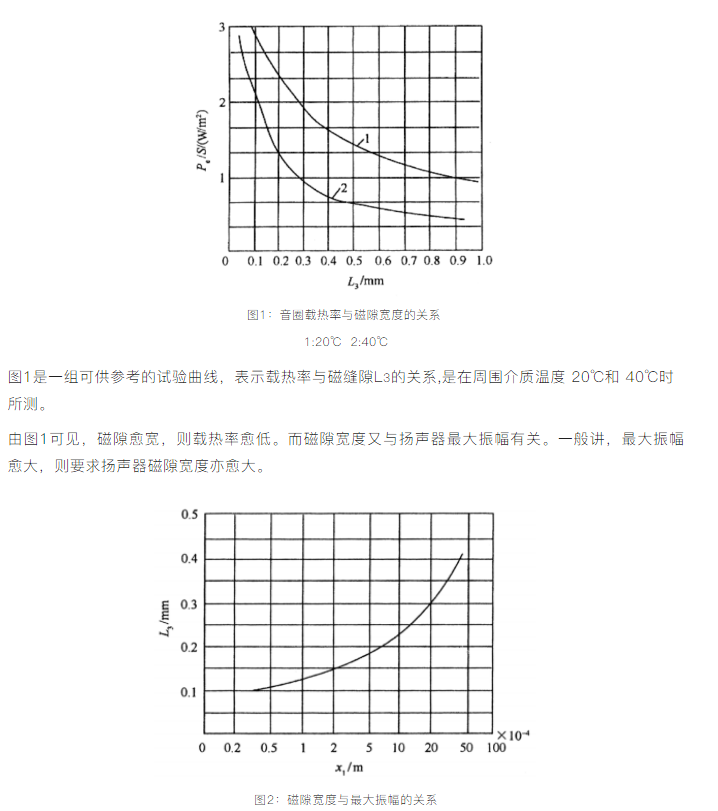
Figure 2 is a reference curve of the relationship between the magnetic gap width \( L_3 \) and the maximum amplitude \( X_1 \).
It can be understood that when the maximum amplitude is relatively large, the required magnetic gap width should also be larger. However, due to the limitation that the magnetic gap width cannot be too large, the two widths are not in a linear relationship. A larger magnetic gap width is beneficial for heat dissipation and process reliability, but it will cause the magnetic flux density to decrease.
Of course, the magnetic gap width also depends on our experience, such as: the approximate thickness of the voice coil, how much space is left before and after the voice coil, etc. It can maximize the pass rate under the current assembly process conditions.
The magnetic gap width can also be determined based on the speaker's aperture. Generally speaking, the larger the speaker's aperture, the larger the magnetic gap width.
There is also a piece of experience for reference: increasing the magnetic gap width will reduce the sensitivity, but the playback sound of the final speaker will be cleaner.
Once the magnetic gap width is determined, the heat transfer rate \( \frac{P_e}{S} \) can be obtained from Figure 1. Since the thermal power of the voice coil \( P_e \) is known, the area of the voice coil \( S \) can be calculated.
There is a certain corresponding relationship between the diameter and height of the voice coil. Let the height ratio be \( K \), then
\( K = \frac{d}{h} \)
Where \( d \) is the diameter of the voice coil;
\( h \) is the height of the voice coil.
For heat dissipation, the larger the speaker power, the larger the ratio \( K \). For high-power speakers, the \( K \) value is 4 to 6; for low-power speakers, the \( K \) value is 3 to 4.
From this, the diameter \( d \) and height \( h \) of the voice coil can be calculated, that is,
\( d = \sqrt{\frac{S}{K \pi}} \)
\( h = \frac{d}{K} \)

Follow Us
Follow Us
 Company Address: No. 98, Fenghuang West Road, Hailing District, Taizhou City
 Service Hotline: 400-006-1982
 Service Phone: 0523-86219066
 Company Email: fs.wu@electronic-tech.cn
 Company Website: http://www.tzfsdz.com/